Condition: Refurbished
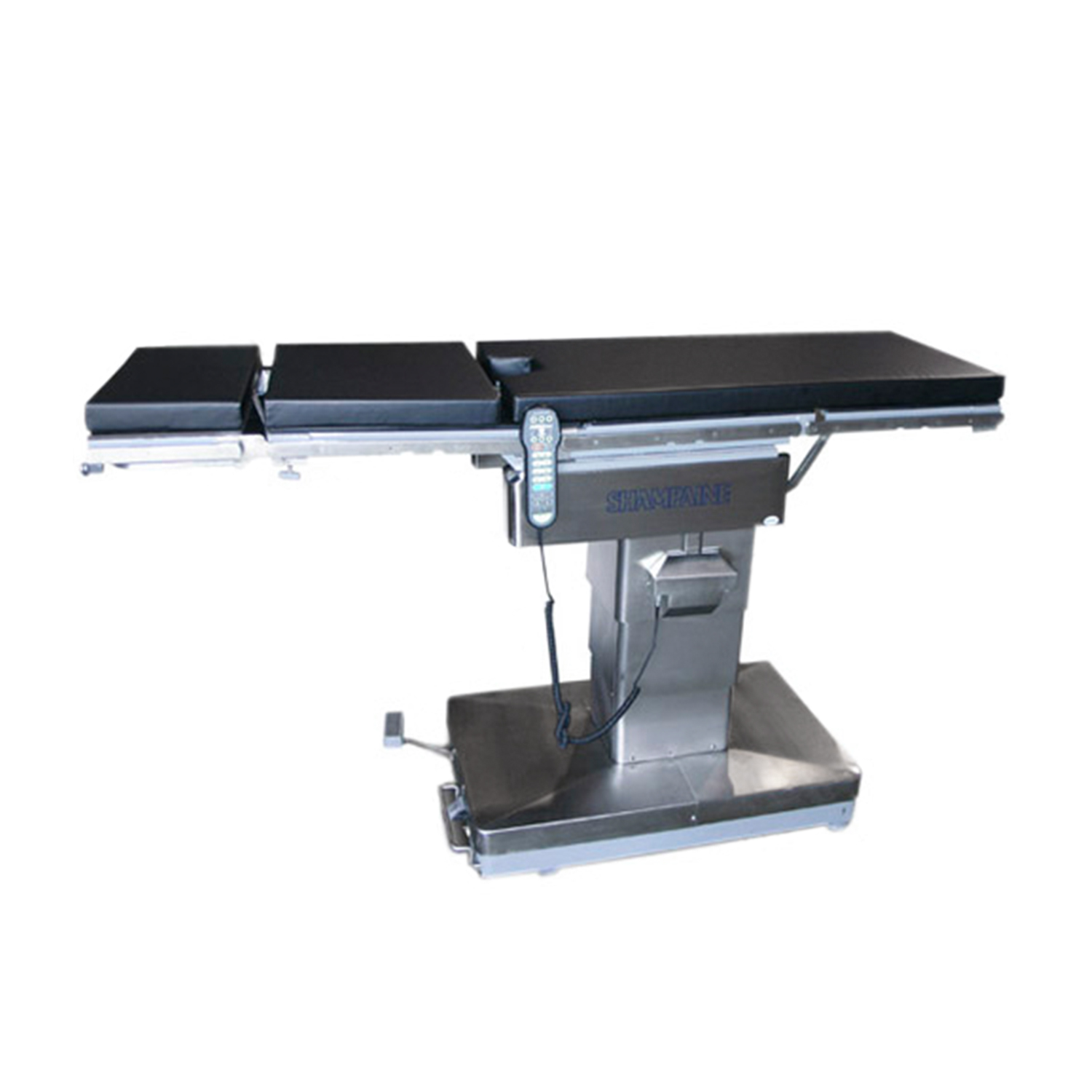
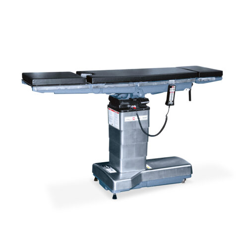
Shampaine 5100B Surgical Table
$0.00
Description
Shampaine 5100B Major Surgical Tables
The 5100B major surgical tables provide flexible articulation for complete patient positioning. Through the use of Electroluminescent (EL) technology, the 5100 series tables are the only tables available with “Full-Function Key Illumination”. These tables have a longitudinal slide feature for full length image amplification. Each of the five table sections, including the 15″ leg extension, come standard with a built-in x-ray cassette tunnel. These tables are capable of returning to the horizontal position (true level) through the convenience of one button activation. The 5100B is battery-powered. The table may be operated with or without the power cord connected. Mains power is only required to recharge the battery. The battery recharge system will restore completely discharged batteries to 80% of full charge within eight hours (8) and bring the table to a full charge within twelve (12) hours of continuous charging.
Design Features
The base houses the following components:
Low Voltage Control Box
Pump/Motor Assembly
Batteries
Hydraulic Manifold Block
Solenoid Valves
AC Power Input Module
Manual Foot Pump
Applications
These tables are designed for use in major surgical suites, ambulatory theaters and medical operatories where accurate patient positioning is critical. They are particularly adaptable to those procedures requiring mobile image amplification equipment without use of a special x-ray top. They also incorporate a backlit primary hand pendant that will facilitate proper patient positioning in low-level lighting situations (i.e. – endoscopy procedures).
Standards and Codes
These tables have been designed to conform to the requirements of:
Underwriters Laboratories
Canadian Standards Association
International Electrotechnical Commission
Patient Positioning Capabilities
Patient lifting capacity is 500 lbs. (227 kg). This means the TABLE UP, TABLE DOWN, Trendelenburg, and REVERSE Trendelenburg functions can be utilized with a 500 lb. patient positioned on the table with the tabletop centered over the column.
Patient articulation capacity is 400 lbs. (181 kg). This means that a 400 lb. patient can be moved into any of the standard procedural positions.
Control System
The primary control system is a dual microprocessor configuration with one circuit board located in the pendant receptacle box and one located in the primary hand pendant. These microprocessors allow actuation of the solenoid valves through the primary hand pendant controls.
Primary Hand Pendant
In addition to the standard table functions, the hand pendant includes the following special features: Return to Level, Patient Orientation, Battery Strength Indicator and Drawer/Service LED Indicators. The Return to Level feature moves the table to a horizontal (true level) position in the correct anatomical sequence. Patient Orientation adjusts all functions relative to the patient’s position on the table (Normal or Reversed). The Battery Strength Indicator continuously monitors the status of the battery and indicates when the table should be plugged in to recharge the battery. The DWR Indicator will illuminate to indicate that the Auxiliary Pendant Drawer is open, diverting power away from the Primary Hand Pendant. The SERV Indicator advises that there is a potential problem, requiring notification of an authorized Service Representative.
Table Function Keys are as follows:
START/STOP activates and deactivates the hand pendant. When the START/STOP key is pressed, all function keys are illuminated and activated for 30 seconds, and will remain illuminated and active for 30 seconds after any function key is pressed. At any time during table activation, the START/STOP key can be pressed to stop the table motion. The START/STOP key remains constantly illuminated to help the user easily activate the pendant, even in low-level lighting situations.
FLOOR UNLOCK/LOCK extends and retracts the three self-leveling feet. Pressing the LOCK key extends the feet, securely locking the table to the floor. For safety, the table will not operate unless the floor locks are engaged. Pressing the UNLOCK key retracts the feet, allowing the table to be easily relocated. Visual confirmation is provided via illumination of the unlock/lock indicators on the hand pendant.
Patient Position Functions Keys are as follows:
BACK UP/BACK DOWN raises the back section 90° above or lowers it 30° below horizontal. Note: When the back section is raised above 25°, the KIDNEY UP function will be disabled.
TABLE UP/TABLE DOWN elevates/descends the entire table top to any position from 28″ to 43″ (711 to 1092mm) above the floor.
LEG UP/LEG DOWN raises the leg section 70° above or lowers it 95° below horizontal.
Trendelenburg/REVERSE Trendelenburg tilts the entire table top about the transverse axis, positioning the head of the table 25° below or above horizontal.
SLIDE FORWARD/SLIDE REVERSE slides the table top longitudinally 8″ (203mm).
TILT LEFT/TILT RIGHT tilts the entire table top laterally up to 18° left or right.
KIDNEY UP/KIDNEY DOWN raises the kidney elevator 2-1/2″ (64mm) above the table surface or retracts it. Note: A built-in safety feature limits the back section from being raised more than 25° while the kidney elevator is up.
FLEX/REFLEX lowers the back section with Reverse Trendelenburg to form an inverted vee (jackknife) of 150° and/or raises the back section with Trendelenburg to form a vee of 90°.
LEVEL brings the table top to a level position in the correct anatomical sequence (to prevent any undue trauma to the patient).
NORMAL/REVERSE table orientation re-orients the hand pendant so that the function keys will operate the table sections coincidental with the patient’s position on the table. Visual confirmation is provided on the hand pendant by illuminating the manual foot pump indicator at the base of the table on the table diagram. In the NORMAL orientation, the manual foot pump indicator will be green and located under the patient’s head. In the REVERSE orientation (used when the patient is reversed on the table), the manual foot pump indicator will be yellow and located under the patient’s feet on the table diagram. This visual indication coincides with the actual location of the manual foot pump on the base of the table, providing an easy reference for the operator to ensure proper table orientation.
Hydraulic System
The hydraulic system is powered by a 24-volt DC electric motor and provides power for all table movements. Solenoid valves direct fluid to steel hydraulic cylinders, and a safety relief valve is provided.
Operating Controls
Base
Mains on/off switch
DC circuit break switch/fuses
Line cord receptacle
Auxiliary hand pendant
Manual foot pump
Primary Control Pendant
Hand pendant actuated floor locks
Battery strength indicator
Articulation switches (Patient Positioning)
Return to Level
Patient Orientation
START/STOP
Pendant Receptacle Box
Hand pendant/footswitch connection
Circuit board (microprocessor)
Standard Accessories
Tables are supplied with 2″ or 4″ regular or Sofpad mattress sets.
X-ray cassette holder
Hydraulically-powered kidney elevator
Primary hand pendant
Auxiliary hand pendant
Restraint strap (1)
15″ Radiolucent leg extension
Power cord
Snap lock armboards/pads (2)
Optional Accessories
Cardiovascular accessories
General accessories
Neurosurgical accessories
OB/GYN accessories
Ophthalmic accessories
Orthopedic accessories
Urological accessories

